


General News
How to Size Energy Storage for a PV Plant (off grid solar system)?
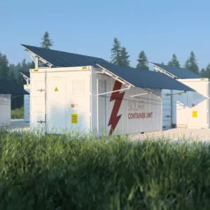
Designing an off grid solar system or a hybrid PV plant that must ride through grid outages hinges on one decision: how much storage you really need. The guide below turns that decision into a repeatable process you can apply to homes, commercial sites, or small industrial loads—anchored in real specifications from Baufar’s PV kits, batteries, and inverters for on-site validation.
1) Analyze the load in depth
1.1 Identify load type and criticality
Residential, commercial, and industrial loads behave differently (evening peaks at homes; weekday daytime peaks in offices; process-driven profiles in factories). Mark which loads are critical (must run during outages) versus deferrable (can pause).
1.2 Build a power inventory
List each device’s rated power (kW), surge/starting power, and usage pattern. Use nameplates, AMI/EMS logs, or historical bills.
Example: A plant with 500 kW running power may peak at ~600 kW when several motors start.
1.3 Map time-of-use
Create a 24-hour profile (15-minute granularity if possible). Typical households peak 18:00–22:00; offices 09:00–18:00; factories follow shifts.
2) Set clear storage design objectives
2.1 Backup duration
Define how many hours storage must support the critical load after a grid loss (or permanently for a fully off grid solar system). Hospitals/data centers may require ≥8 h; households often need 2–6 h.
2.2 PV smoothing and power quality
If PV intermittency must be buffered, specify the ramp rate and allowed power deviation.
Example: A 10 MW plant may require storage to keep net power within ±10% during rapid irradiance changes within 1 minute.
Tip: Pre-configured kits help check feasibility. Baufar’s 10 kW off-grid kit bundles 19×550 W modules (~10.45 kWp), an off-grid inverter, and a 20 kWh LiFePO₄ battery—useful as a reference layout for small sites.
3) Calculate the energy capacity (kWh)
3.1 Backup-hours method
Storage (kWh)min=Avg. critical load (kW)×Backup hours (h)\text{Storage (kWh)}_{\min} = \text{Avg. critical load (kW)} \times \text{Backup hours (h)}
Example: 200 kW × 4 h = 800 kWh.
3.2 PV–load mismatch method
Compare the PV generation curve with the load curve. The daily surplus that must shift to night (sum of positive gaps) is the minimum daily storage throughput.
Example: If ~300 kWh must be shifted nightly, storage must at least handle that energy with room for losses.
3.3 Safety factor
Multiply the larger result by a safety factor (typ. 1.2–1.5) to cover weather, forecasting error, and degradation.
4) Correct for round-trip efficiency and usable DoD
Storage is not 100% efficient, and you should not cycle batteries from 0% to 100% every day.
-
Round-trip efficiency (RTE): include DC battery + inverter + wiring losses. Small off-grid inverters commonly reach ~96–97% efficiency; modern grid-tie units list up to ~98%—use your actual topology for RTE.
-
Usable depth of discharge (DoD): LiFePO₄ systems are often designed for ~60–90% DoD to extend life. Set DoD based on warranty and cycle-life targets.
Sizing correction:
Rated capacity (kWh)=Required delivered energy (kWh)RTE×DoD\text{Rated capacity (kWh)}=\frac{\text{Required delivered energy (kWh)}}{\text{RTE} \times \text{DoD}}
Worked example (continuing 800 kWh):
Assume RTE = 0.85 and DoD = 0.60 → Rated capacity ≈ 800 / (0.85×0.60) ≈ 1,568 kWh.
Apply safety factor 1.2 → ~1,882 kWh.
5) Power constraints: kW matters as much as kWh
Your battery and inverter must meet:
-
Continuous power (kW) ≥ peak critical load after any shedding.
-
Surge/starting power: motors and compressors can demand 2–6× nameplate for seconds.
-
Battery C-rate: Make sure the battery can safely sustain the discharge current needed for the inverter’s rated power.
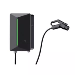
Check real specs when validating a design. Baufar lists MPPT windows and efficiency for inverters (e.g., 5 kW off-grid inverter MPPT 90–430 V, efficiency 96.6%; 10 kW three-phase grid-tie MPPT 160–850 V, max DC 1000 V), which helps confirm string sizing and conversion losses in your RTE assumption.
6) Selecting battery building blocks and communication
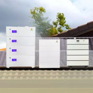
Modular 51.2 V LiFePO₄ packs (5–10 kWh each) make it straightforward to scale to hundreds of kWh and integrate with mainstream inverters; look for CAN/RS485 communication and published certifications (CE, UN38.3, MSDS, IEC). Baufar’s 10 kWh wall-mounted and 15 kWh roller batteries illustrate these attributes and a 5-year warranty on selected models.
7) Putting it all together — a step-by-step recipe
-
Define scope & criticality
-
Decide if you are fully off grid solar system or grid-interactive.
-
Split loads into critical and deferrable.
-
-
Build the 24-h profile
-
Record average and peak power (kW) and total energy (kWh).
-
Identify motor surges and process constraints.
-
-
Set design targets
-
Backup hours; smoothing response; black-start needs.
-
Allowed state of charge (SoC) operating band for longevity.
-
-
Size energy (kWh)
-
Max{Backup-hours method, PV–load mismatch} × safety factor.
-
Correct for RTE and DoD to get rated capacity.
-
-
Check power (kW)
-
Inverter continuous & surge ratings ≥ required kW.
-
Battery C-rate supports inverter output and surge.
-
-
Choose building blocks
-
Select modular 51.2 V units (e.g., 10 kWh) and stack to target kWh.
-
Verify BMS protocol (CAN/RS485) with the chosen inverter.
-
-
Validate with real products
-
Cross-check against a reference kit (e.g., Baufar 10 kW off-grid kit with ~10.45 kWp array and 20 kWh storage) and adjust for your site’s backup hours and DoD.
-
8) Economics and ROI
-
CAPEX: batteries, inverters, BOS (racks/cables/EMS), installation.
-
OPEX: augmentation (if planned), replacements, routine maintenance.
-
Benefits: avoided outage losses, diesel offset, tariff arbitrage (hybrid), export compliance, and improved power quality.
Iterate capacity until NPV/IRR meets your threshold; if the step from (say) 1.8 MWh to 2.2 MWh adds cost without proportionate benefit, cap the design at the smaller size.
9) Compliance & reliability checks
-
Verify certifications (e.g., CE, UN38.3, MSDS, IEC) on the selected battery model and ensure documentation is available for shipping and commissioning.
-
Confirm warranty terms (several Baufar models show 5 years battery warranty) and expected cycle life under your DoD and temperature profile.
Example: From concept to bill of materials
-
Site: small commercial campus, critical load 200 kW, backup 4 h.
-
Energy: 200×4=800 kWh → with RTE 0.85 & DoD 0.60 → 1,568 kWh → ×1.2 safety → ≈1.88 MWh rated.
-
Power: inverter farm sized for ≥200 kW continuous and surge margin.
-
Blocks: use 51.2 V 10 kWh or 15 kWh LiFePO₄ modules with CAN/RS485, paralleled into racks until ≈1.9 MWh is reached; select inverters with published MPPT windows/efficiency to support the PV array and keep RTE assumptions realistic.
Where Baufar fits
-
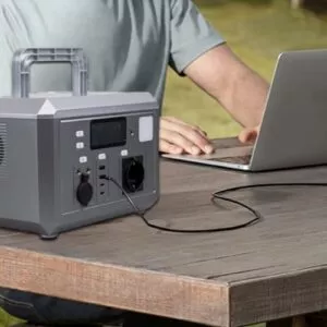
Reference kit: 10 kW off-grid system (array, off-grid inverter, ~20 kWh LiFePO₄, BOS) for small sites and as a design benchmark.
-
Battery modules: 51.2 V 10 kWh wall-mount and 15 kWh roller options; modular, inverter-compatible, with listed certifications and communications.
-
Inverters: published MPPT ranges and efficiencies to help refine RTE and string sizing during design reviews.
Final checklist (copy-paste for your project)
-
Load profile completed (kW & kWh; surge noted)
-
Backup hours / smoothing target defined
-
Base kWh sized; safety factor applied
-
RTE & DoD corrections applied; rated kWh finalized
-
Inverter kW (cont./surge) & battery C-rate verified
-
Communication (CAN/RS485) and certifications (CE/UN38.3/MSDS/IEC) checked
-
ROI/IRR meets target; bill of materials aligned with off grid solar system scope
 Solar Panel
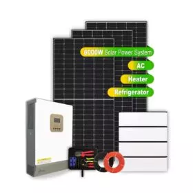 Solar Power System